The method of motion of a planetary gear structure is different from traditional parallel gears. The planetary speed reducer has six gear contacting surfaces with a larger area that can distribute the loading evenly over 360 degrees. Multiple gear surfaces share the instantaneous impact loading evenly which make them more resistant to the impact from higher torque. The housing and beaning parts will not be damaged and crack due to high loading.

Features
Transmission Principle of Planetary Gear Reducer
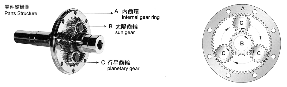
The transmission structure of the planetary speed reducer has the highest geared gear motor efficiency among all the combinations.Its basic transmission structure includes:
(A) Internal GearRing (B) Sun Gear
(C) Planetary Gear(assembled with the planetary carrier)
The driving power through direct connection or link initiates the sun gear. The sun gear then drives the planetary gears assembled with the external gear ring to operate.The whole set of planetary gear system revolves on its own axis and along the external gear ring where the output shaft connected to the planetary carrier achieves the goal of speed reduction.A higher reduction ratio can be achieved by doubling the multiple staged gears and planetary gears.
Characteristics of Planetary Gear Reducer
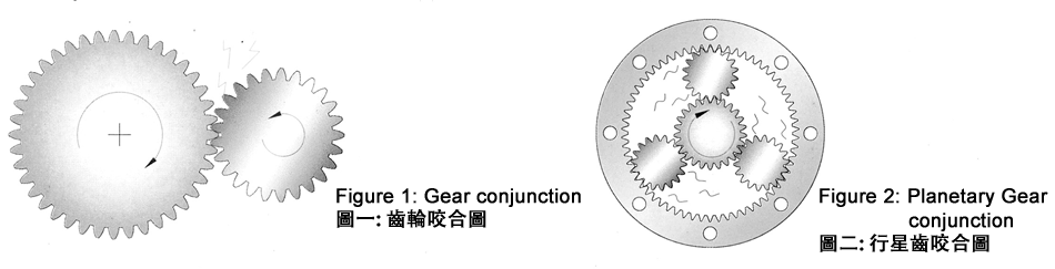
High torque and impact resistance: The method of motion of a planetary gear structure is different from traditional parallel gears.Traditional gears rely on a small number of contact points between two gears to squeeze as the driving force, where all the loadings are concentrated on a few contacting surfaces (Figure 1), making the gears easy to wear and crack.But the planetary speed reducer has six gear contacting surfaces with a larger area that can distribute the loading evenly over 360 degrees.Multiple gear surfaces share the instantaneous impact loading evenly which make them more resistant to the impact from higher torque.The housing and beaning parts will not be damaged and crack due to high loading.
Principle of planetary gear motor and calculation of gear ratio
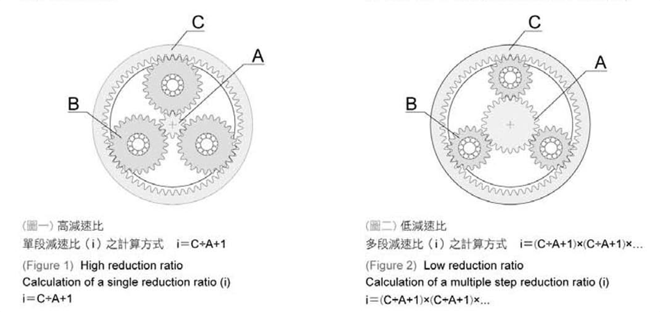
Simple calculation method for the gear ratio of a planetary speed reducer,when step gear or sun gear (A)rotates at a certain speed. Planet gear (B)travel along the internal gear ring (C)in a full round and return to the origin, where the rotation speed is the reduction ratio of that single interval. Because the internal gear ring is common to the same model number, the value of the speed reduction ratio is determined by the tooth number of the sun gear.The lower the tooth numberof the sun gear, the higher the speed reduction ratio(Figure 1).On the contrary, the higher the tooth number of the sun gear, the lower the speed reduction ratio.The actual calculation method is to divide the tooth number of the internal gear ring by the tooth number of the sun gear.The number derived added to the fixed coefficient 1 is then the speed reduction ratio.Multiply the ratios of each single step to obtain the total reduction ratio of that machine.
Dismantling of the planetary gear speed reducer and collocation of transmission components
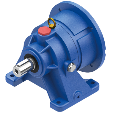
The planetary rack of the planetary speed reducer is floating and embedded inside the gear motor. Only partial removal of some of the parts is required, when disassembling parts and changing ratios for the replacement. There is no need to disassemble the major portion which could cause damage to the parts. The installing flange is a direct connection which is applied to international standard specifications IEC. Customers can select different brands by themselves or install the motor of specific requirements for protective grades. Our company also provides specific sizes including servo, DC, hydraulic, pneumatic turbine speed variator etc.
Technical
Information
.jpg)
Designation

|
j |
Model |
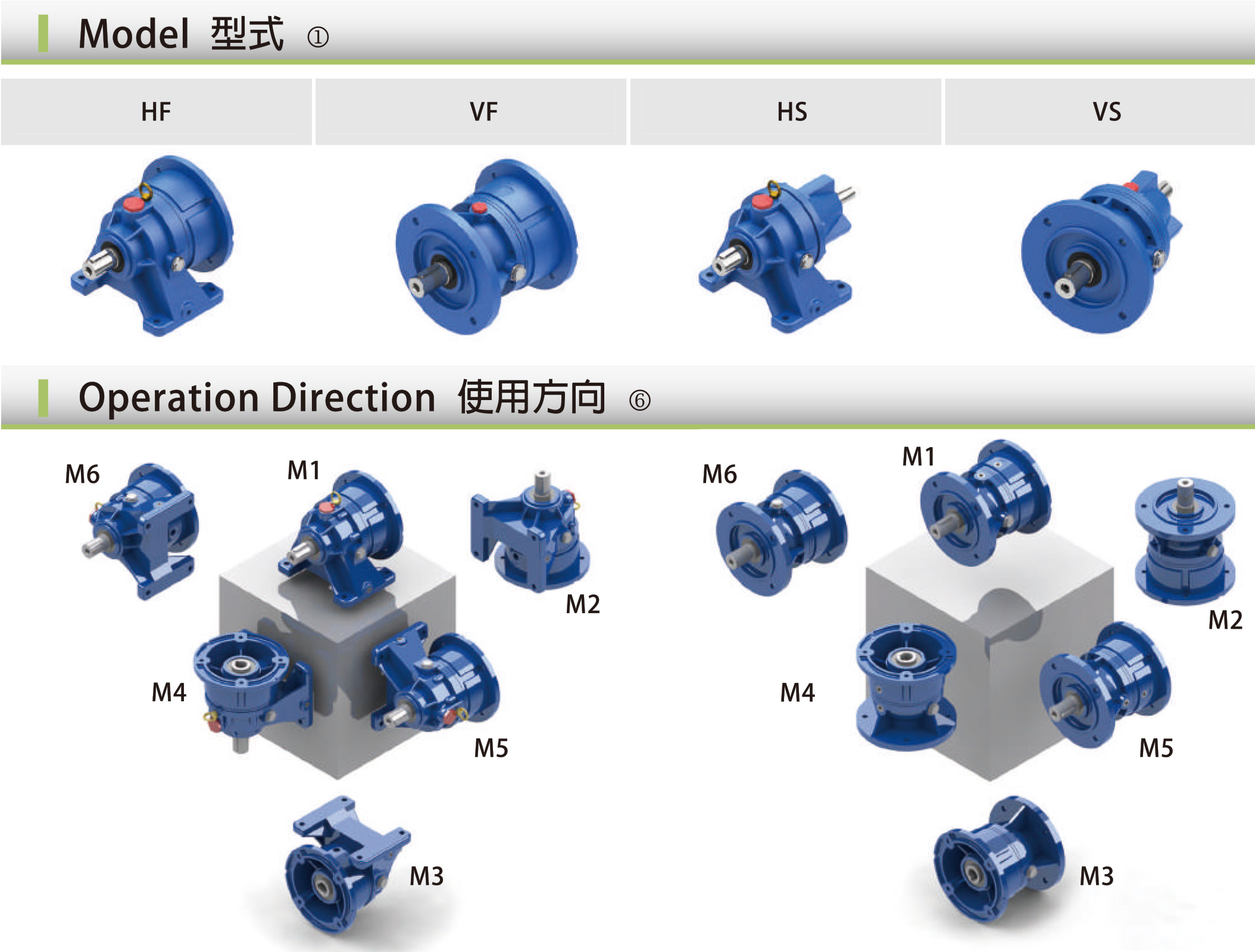
HF: Foot Mount Reducer with IEC Adaptor VF: Flange Mount Reducer with IEC Adaptor HS: Foot Mount Reducer with Input Shaft VS: Flange Mount Reducer with Input Shaft |
|
|
k |
Frame Size |
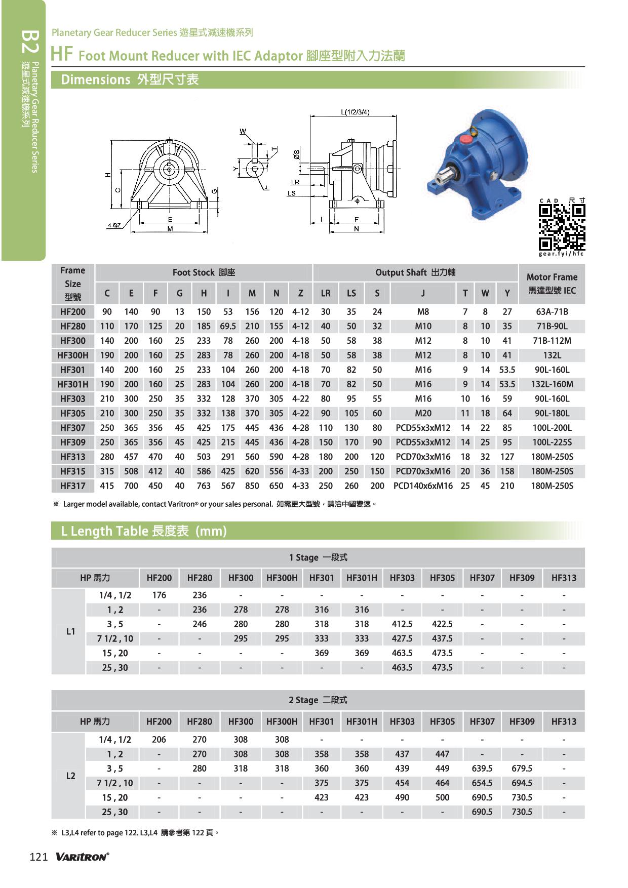
200,280,300,300H,301,301H,303,305,307,309,313 Refer to page 118~120. |
|
|
l |
Stage |
L1, L2, L3, L4, L5 |
|
|
m |
Ratio |
3.48,4.26,5.77,7.20,… Refer to page 118~120. |
|
|
n |
Horse Power |
02,05,1,2,3,5,8,10… Refer to page 118. |
|
|
Servo Motor |
Refer to page 125. |
||
|
o |
Operation Direction
|
M1,M2,M3,…Refer to page 117. |
|
|
|
Suffix (Optional) |
TL: Torque Limiter DC: DC motor WG: Worm Gear BG: Bevel Gear |
|
Dimensions
Applications

Downloads
Product
Inquiry


Address:No.45, Lane 171, Chung Shin Road, Wuku District, New Taipei City, Taiwan
Tel:+886-2-29889598
Fax:+886-2-29850998
Email:[email protected]
Copyright 2014 © Varitron Engineering (Taiwan) Co., Ltd. All Rights Reserved.


